Motivation
Authors: Matija Šavli, Lan Vukušič
My friend Lan Vukusic and I are both hobby beer brewers, but we kept running into the same bottleneck: yeast scarcity. We tried cultivating yeast from the sediment of previous batches in small jars; while this worked, it was inconsistent.
We knew there had to be a better way. We started researching how to optimize the process and landed on the idea of creating a custom bioreactor. By strictly controlling environmental factors—temperature, pH, and oxygen levels—we realized we could not only scale up our yeast production but also guarantee the consistency required for high-quality brewing.
Beyond the practical utility, we had a secondary motive: we wanted to stretch our engineering muscles. We had the theoretical knowledge and the 3D printers, and we wanted to prove to ourselves that we could apply them to build a complex, real-world biological system.
Designing parts
When we started the build, we had a vision for the finished reactor but avoided rigid planning. We knew that in a project like this, the first design is rarely the right one. Instead, we adopted an iterative approach: build, test, fail, and redesign.
We identified the critical subsystems required to make the bioreactor functional:
- The Jar & Lid
- The Mixer
- Motor mount
- Temperature probe mount
- Bubbler (Aeration)
- Electronics housing
Below, we detail the design process for these parts, including the iterations that didn’t make the cut.
Jar lid
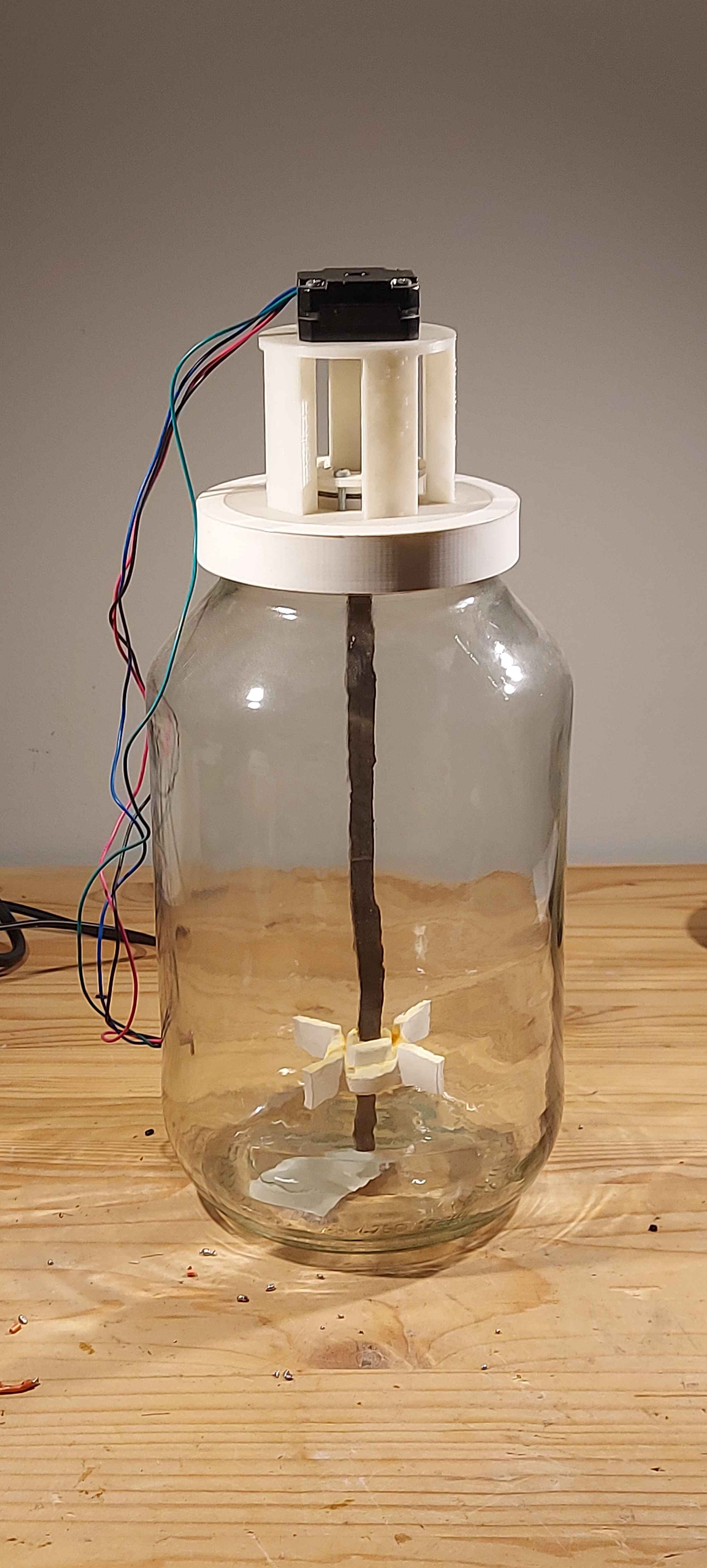
We chose a 5-liter glass pickle jar as our vessel. At approximately 4€, it was a steal—large enough for substantial yeast propagation, easy to sterilize, and chemically inert.
To turn a pickle jar into a reactor, we needed a custom airtight lid to mount our sensors and actuators while maintaining sterility. We modeled the lid in FreeCAD and printed it on a Creality V2.
The Engineering Challenge
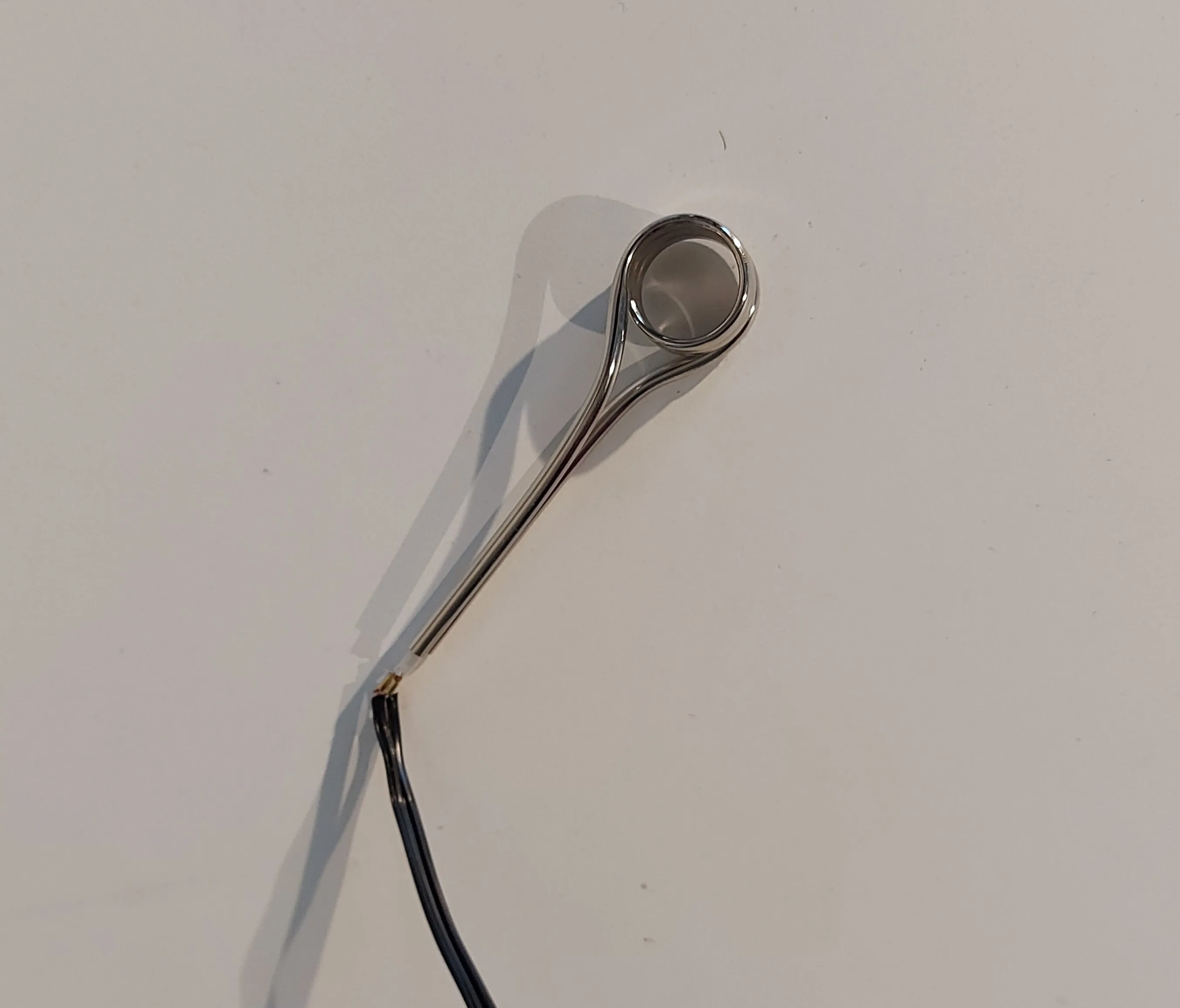
Modeling the thread for a glass jar is deceptively difficult. Unlike standard ISO threads, glass threads often have unique profiles and tolerances. We struggled to measure the exact angle of the glass “teeth,” so we resorted to empirical testing. We printed a series of test rings with varying radii and thread pitches until we found the perfect, airtight fit.
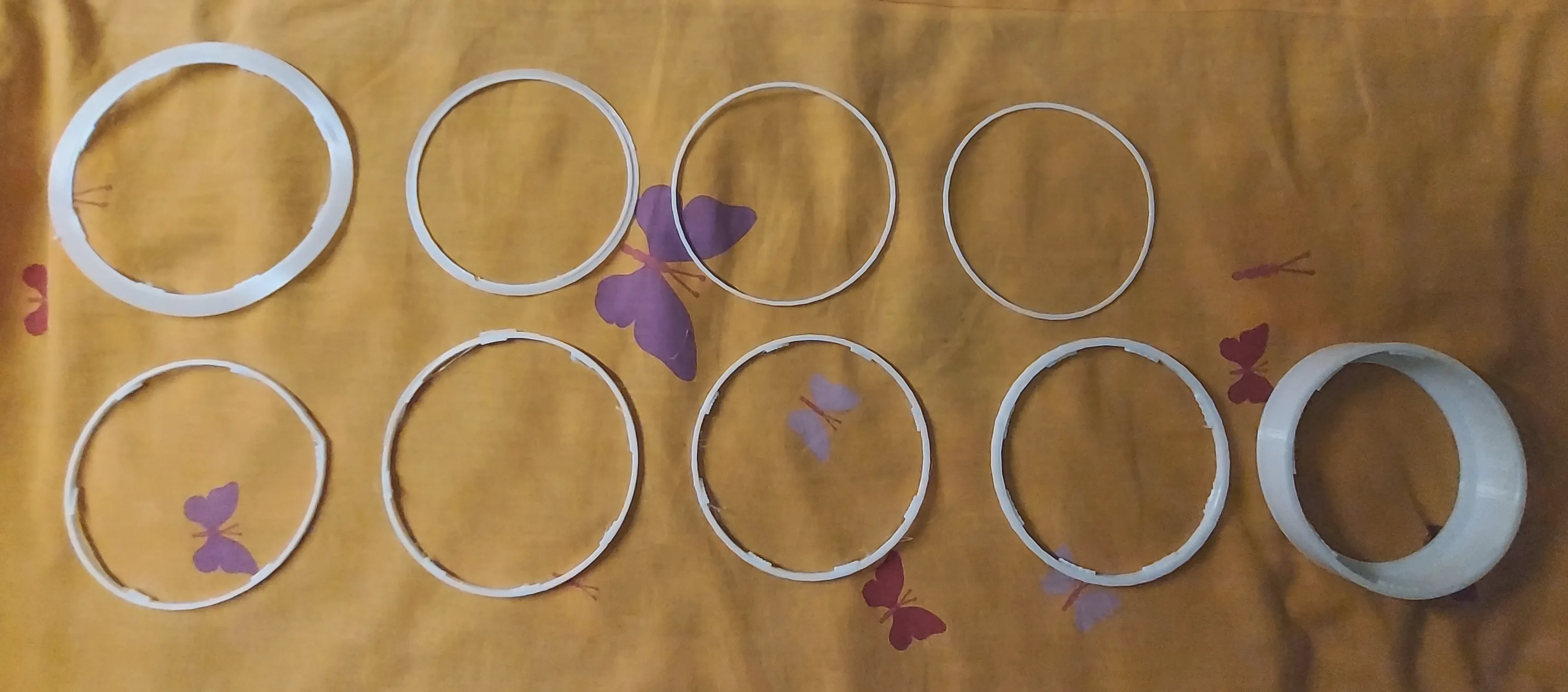
After conducting these tests, we found the ideal fit (shown on the bottom right in the image above).
While determining the correct radius was straightforward, creating the thread geometry required more trial and error. We adjusted the angle of the gripping teeth in CAD until the friction was just right.

The final design printed perfectly and allowed for a tight, secure seal on the jar.
Mixer
Properly mixing the contents of the reactor is crucial. We need to ensure good aeration and prevent sediment formation by distributing micro-organisms evenly throughout the medium.
1. Design Choice: Axial vs. Radial
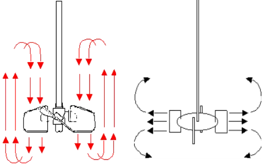
Our first engineering decision was choosing the blade geometry. We considered two main types: axial (marine-style) and radial (turbine-style).
| Mixer Head | Type Name | Pros | Cons |
|---|---|---|---|
| Axial | Marine Propeller | High Flow, Gentle mixing | Low shear (poor gas dispersion) |
| Radial | Rushton Turbine | High Shear (great for bubbles) | Lower vertical circulation |
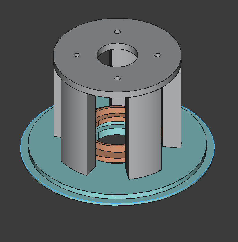
We chose the Radial design (Rushton Turbine) for one specific reason: Gas Dispersion.
In a bioreactor, the limiting factor is usually how much oxygen you can dissolve into the liquid. A radial mixer pushes fluid outward against the jar walls with high energy. This “shear force” smashes the large air bubbles coming from the bottom into tiny micro-bubbles. Smaller bubbles mean more surface area, which translates to more oxygen for the yeast.
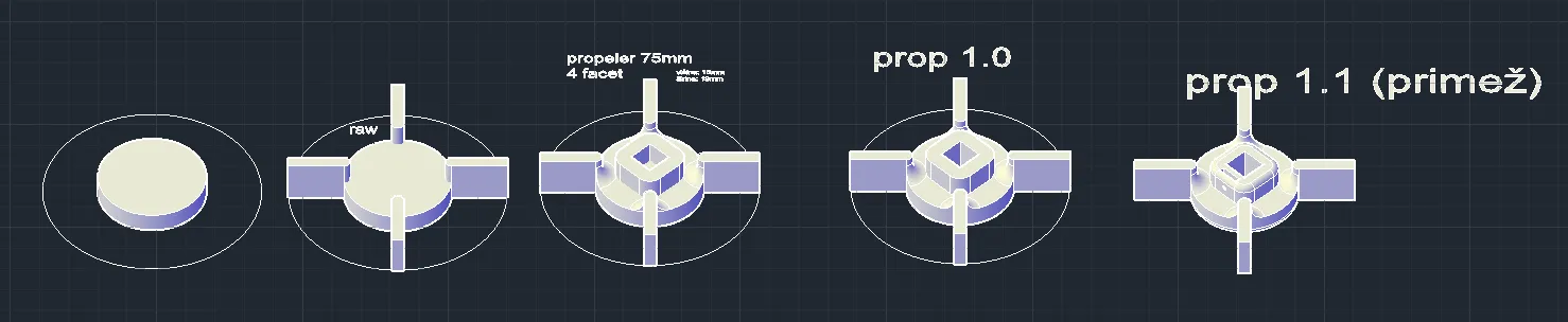
2. Sizing the Turbine With the geometry selected, we sized the blades using standard bioprocess engineering ratios found in literature.
For a reactor with diameter d = 180mm and height h = 220mm, the blade diameter (
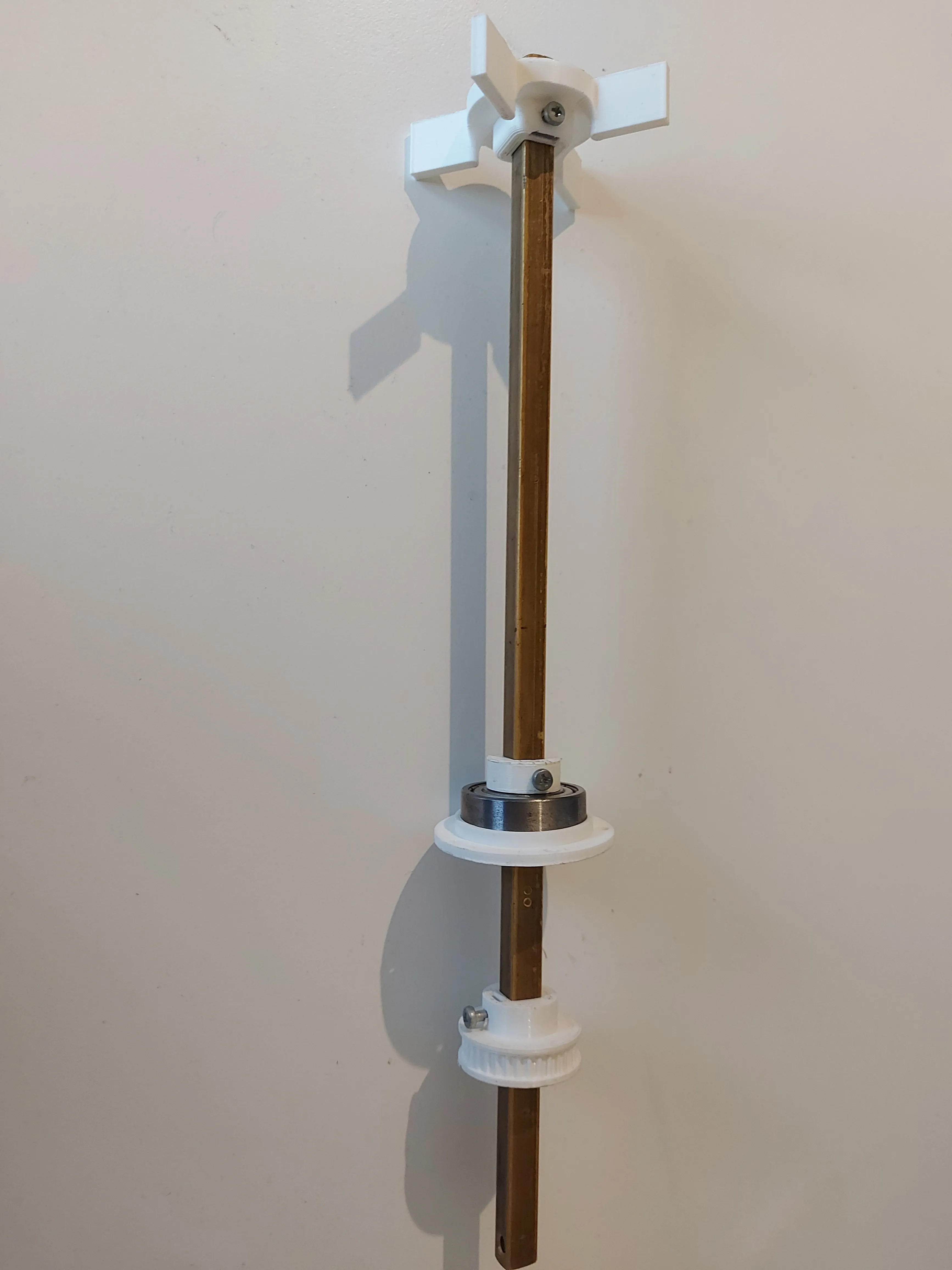
3. The Build We modeled the Rushton turbine in FreeCAD, adding a mounting collar to the design so we could secure it to the shaft with a set screw.
The final assembly uses a square brass rod to transmit torque, with the 3D printed mixing heads secured at the bottom.
Motor and Housing
The “Free” Mistake Initially, we tried to repurpose a stepper motor from an old inkjet printer. It was free, but mounting it was a nightmare. While the torque was actually sufficient for the job, we hit a wall trying to control it. We simply couldn’t get it to rotate consistently with our stepper drivers. Rather than wasting days debugging proprietary wiring schemes or driver incompatibility, we decided to cut our losses and move to a standardized solution.
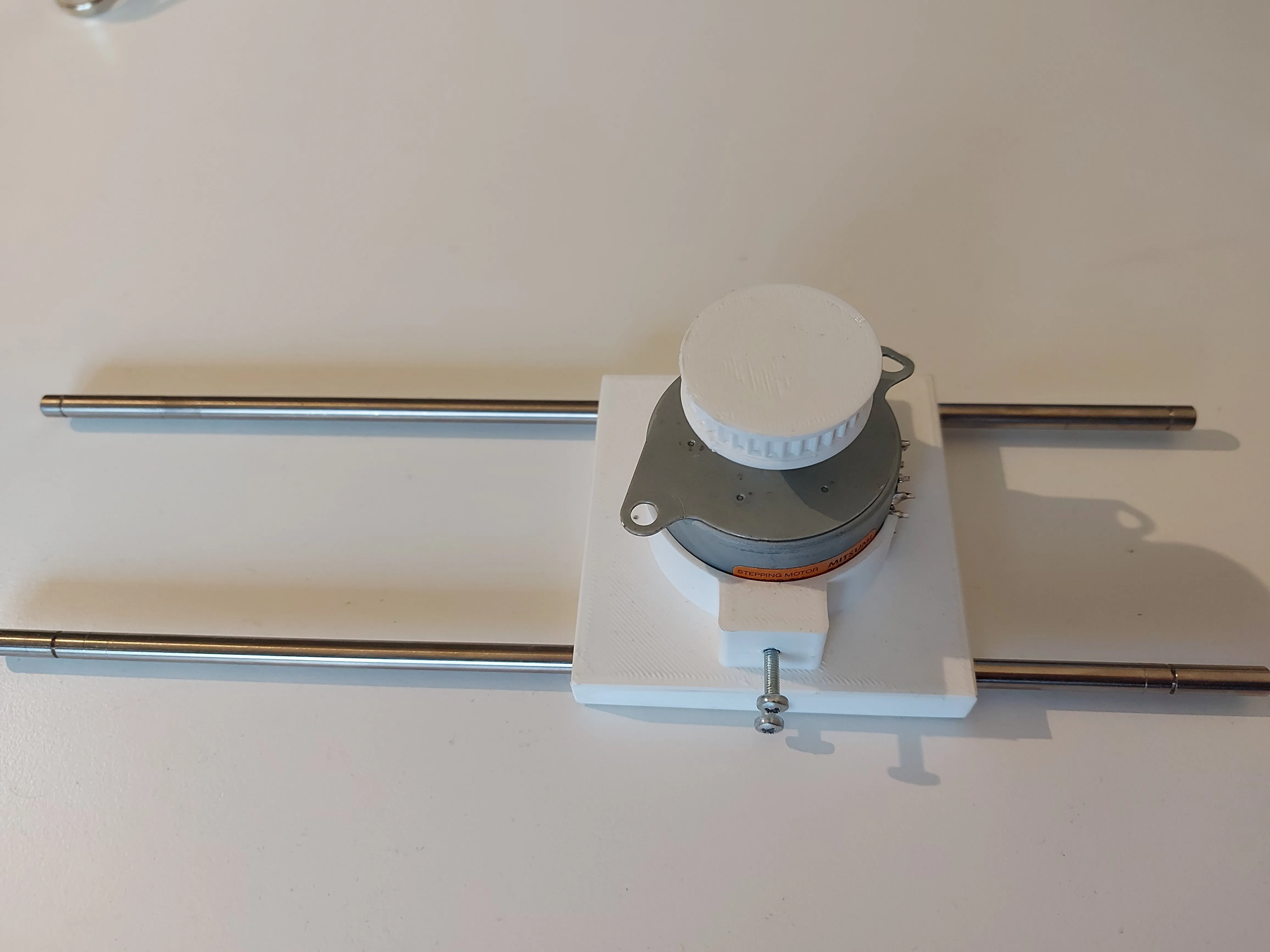
The Upgrade We eventually upgraded to a standard NEMA 17 stepper motor. It is the industry standard for 3D printers for a reason: it offers high torque, precise control, and convenient mounting holes that work with almost any off-the-shelf driver.
To securely attach the NEMA 17 to our lid, we designed a custom motor holder in FreeCAD. This housing ensures the motor stays perfectly aligned with the central mixing shaft while minimizing vibration.
Instead of a complex belt system, we opted for a direct-drive configuration. We designed a custom 3D-printed coupler to connect the motor’s shaft directly to the square brass mixing rod. This simplifies the assembly and reduces the number of moving parts.
Failed Ideas
Science is mostly failure. Before we landed on the direct-drive tower, we tried a complex belt-drive system to keep the motor off-center.
- The Idea: Use a belt to reduce vibration and keep the motor cool.
- The Reality: It was unwieldy and overly complex. Tensioning the belt was a nightmare, and it added necessary points of failure.
- The Lesson: Simple is better. We scrapped it for the direct-drive approach.
Air supply
For oxygenation, we selected a Resun Air 2000 aquarium pump. It provides sufficient airflow to keep the medium oxygenated. To ensure sterility, the air intake passes through a Sartorius Midisart 2000 filter.
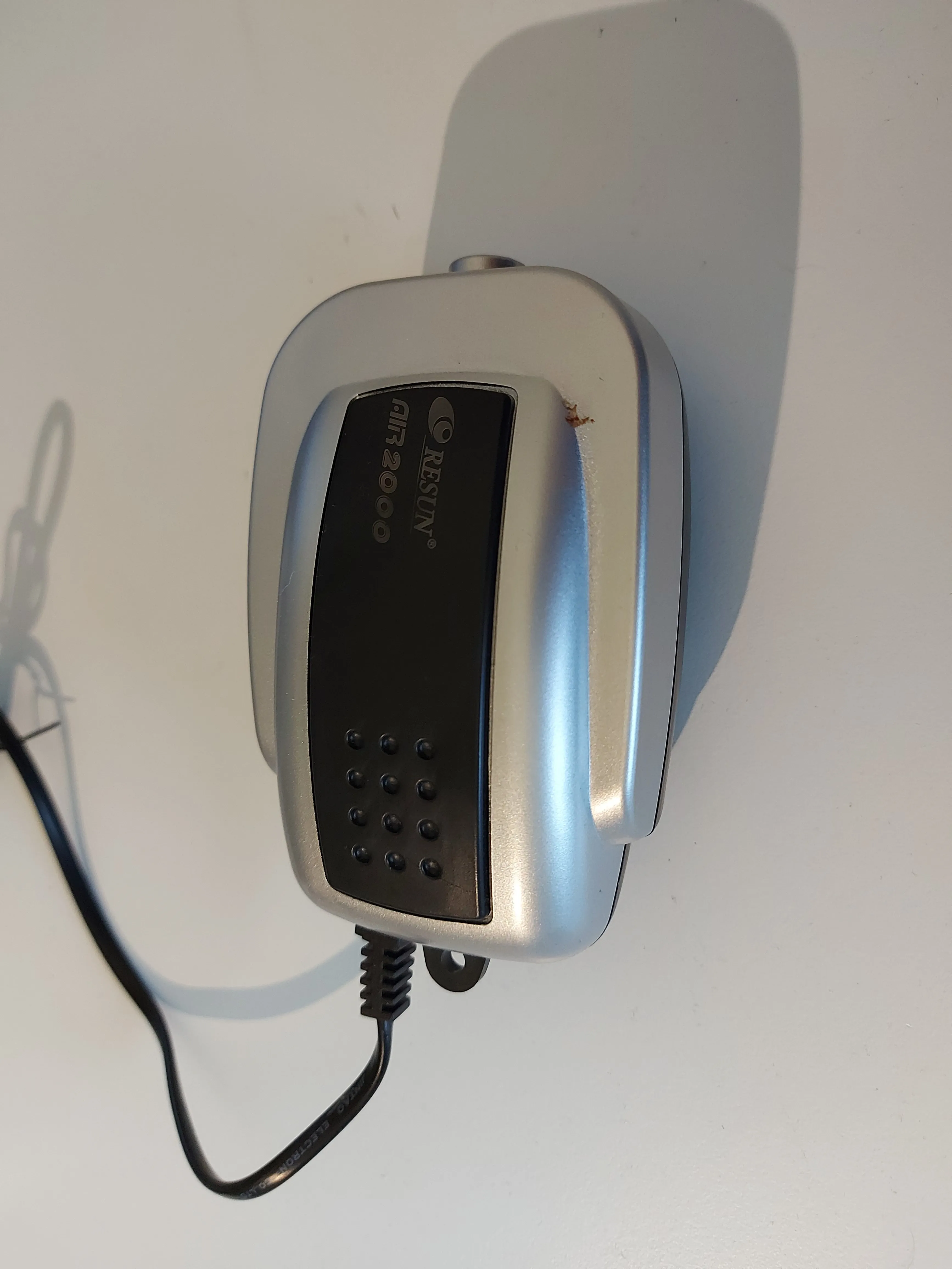
Current Limitation: The pump runs on 220V AC (wall power), while the rest of our system is 12V DC. Right now, the pump is “always on” when plugged in. We haven’t tested the automated cycle yet because we need to install a relay module (or Solid State Relay) to let the low-voltage ESP32 safely switch the high-voltage AC pump on and off.
Electronics and sensors
The brain of the operation is an ESP32-WROOM-32 microcontroller. This board was chosen for its built-in WiFi and Bluetooth capabilities, which will eventually allow us to monitor the fermentation process remotely. To keep things modular during development, we wired everything up on a breadboard first. This includes the ESP32, a stepper driver, and the power management rails.
Schematics and PCB
The schematics were never actualized and printed, but a Ki-Cad project for the production version is made and available on github.
⚠️ Work in Progress Note: The electronics design shown below is currently experimental. We have identified some potential safety issues with the heater driver circuit (specifically regarding “fail-safe” states) that we are redesigning. If you look at the GitHub files, please treat them as a draft, not a final production-ready board.

Prototyping Components: Temperature Control
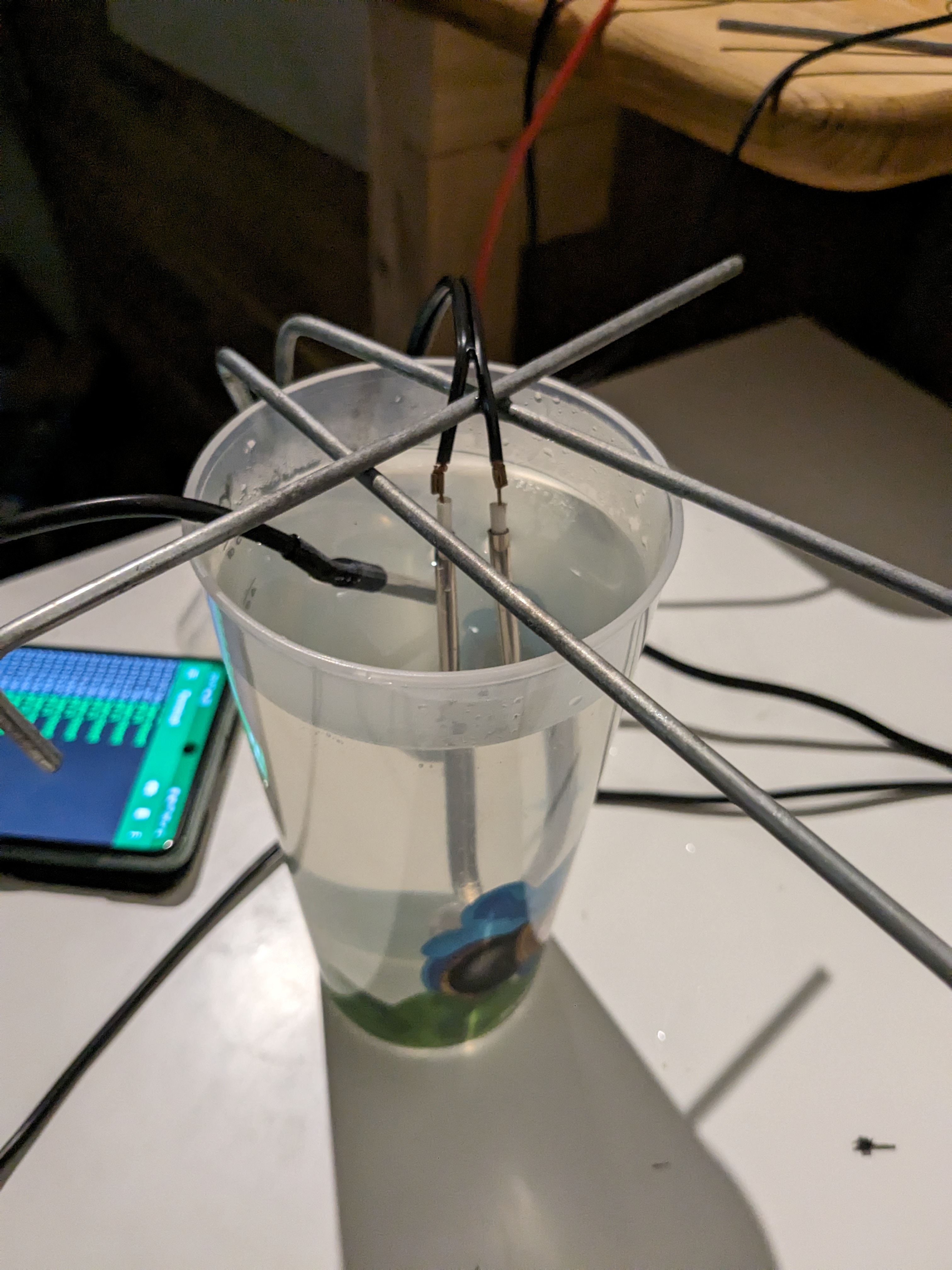
Yeast is sensitive. To keep our cultures happy, we need to maintain a specific temperature range (typically between 18°C and 24°C). For this, we used a small 12V immersion heating element.
Validation Testing Before risking a batch of actual yeast, we needed to validate our control logic. We set up a “high-tech simulation environment”—a plastic cup of water—to ensure our code wouldn’t accidentally boil the medium.
The Power Plant
To run the heater, the high-torque stepper motor, and the ESP32 simultaneously, we needed a beefy 12V DC source. A standard AC adapter wouldn’t cut it.
Instead of buying an expensive bench supply, we scavenged a server power supply (HP HSTNS-PL23B) from an old data center rack.
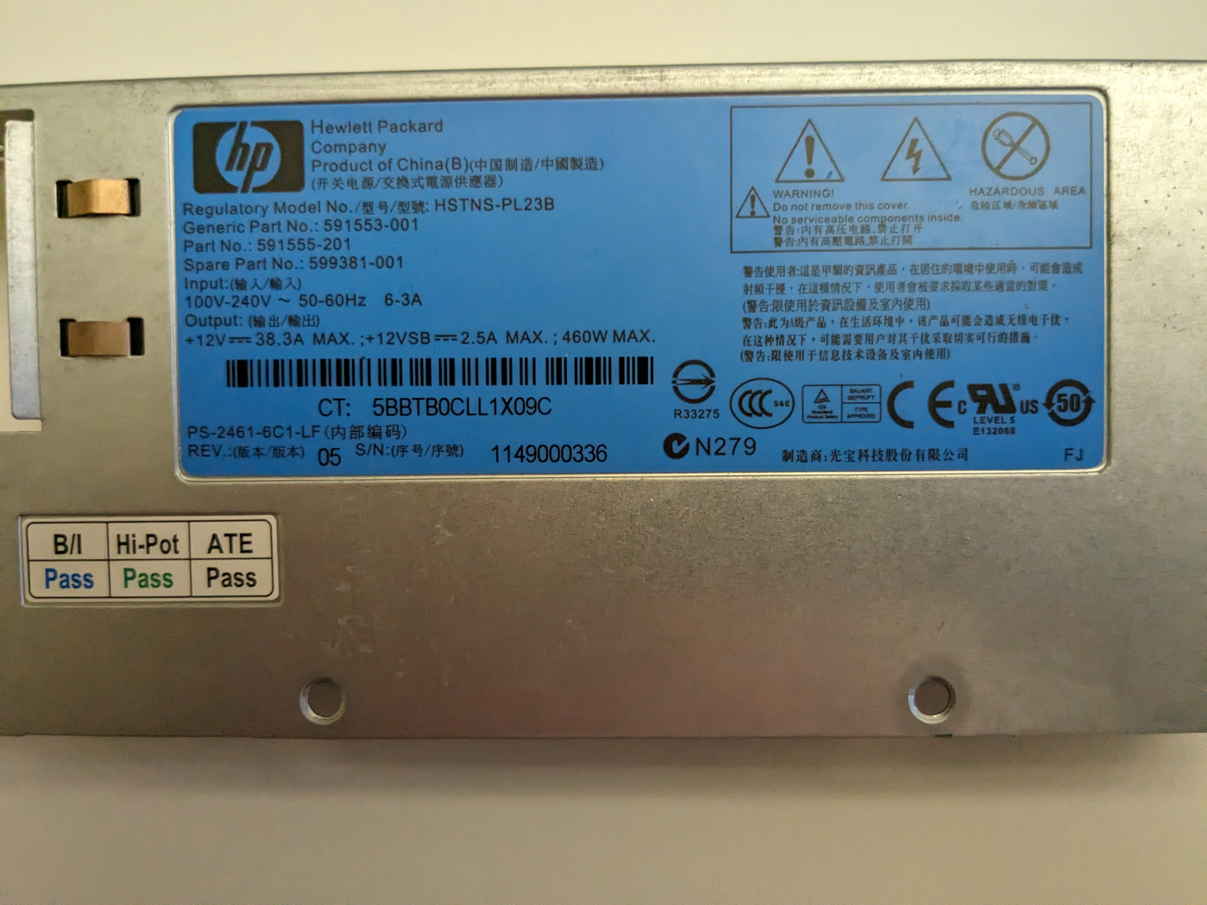
- Specs: 12V @ 38.3A (460W Max)
- The Verdict: It is completely overkill for this project, but that’s exactly what we wanted. It guarantees stable voltage rails no matter how hard the motor or heater draws current, preventing brownouts that could reset the microcontroller.
The Logic (Firmware)
Hardware is a paperweight without code. We developed the firmware using PlatformIO (VS Code) rather than the standard Arduino IDE, as it offers better library management.
The Control Strategy
For version v0.1, we implemented a Bang-Bang control loop. While PID control is smoother, a large jar of water has high thermal mass (it heats and cools slowly), making simple Bang-Bang control surprisingly effective:
- Read temperature sensor.
- Is it too cold? Turn heater ON.
- Is it warm enough? Turn heater OFF.
We also implemented safety checks. If the sensor returns -127 (the Dallas library’s error code for “disconnected”), the system immediately shuts down the heater to prevent a runaway thermal event.
Code snippet (v0.1):
Note: The relay logic is inverted (LOW = ON) because most relay modules are “Active Low”.
#include <Arduino.h>
#include <OneWire.h>
#include <DallasTemperature.h>

// Pin Definitions
#define ONE_WIRE_BUS 4
#define GATE_PIN 2

// Configuration
#define TEMP_WANTED 43.0 // High temp for stress testing heater

// Sensor Setup
OneWire oneWire(ONE_WIRE_BUS);
DallasTemperature sensors(&oneWire);

// Global Variables
unsigned long initial_time = 0;
float initial_temp = 0;
bool has_reached_temp = false;

void setup()
{
  Serial.begin(9600);
  sensors.begin();
  delay(500);

  // GATE SETUP
  pinMode(GATE_PIN, OUTPUT);

  // Reset metrics
  initial_time = millis();
  initial_temp = sensors.getTempCByIndex(0);
}

void loop()
{
  sensors.requestTemperatures();
  float temp = sensors.getTempCByIndex(0);
  Serial.print(temp);
  Serial.print(" C  |  ");
  delay(500);

  // Failsafe: Check if sensor is unplugged (returns -127)
  if (temp - (-127.0) < 0.0001)
  {
    Serial.println("No sensor found");
    delay(1000);
    return;
  }

  // Bang-Bang Control Logic
  if (temp < TEMP_WANTED)
  {
    // INVERTED PINS (LOW = Relay ON)
    digitalWrite(GATE_PIN, LOW);
    Serial.print("Gate opened (Heater ON)  |  ");
  }
  else
  {
    // INVERTED PINS (HIGH = Relay OFF)
    digitalWrite(GATE_PIN, HIGH);
    Serial.print("Gate closed (Heater OFF) |  ");

    // Performance Logging: Record time to reach target
    if (!has_reached_temp)
    {
      has_reached_temp = true;
      Serial.println("");
      Serial.print("Time to reach temp: ");
      unsigned long time = millis() - initial_time;
      Serial.print(time / 1000);
      Serial.print(" s || ");
      Serial.print("Temp delta: ");
      Serial.print(temp - initial_temp);
      Serial.println(" C");
    }
  }

  // Runtime logger
  unsigned long time = millis() - initial_time;
  Serial.print(time / 1000);
  Serial.println(" s");
}
The Cost of Materials
Total cost? Still cheaper than buying new yeast every weekend, even with the motor upgrade.
| Item | Cost (Approx) | Notes |
|---|---|---|
| Glass Jar (5L) | 4€ | Local hardware store (Pickle jar) |
| NEMA 17 Motor | 15€ | Upgraded from salvaged printer motor |
| ESP32 Dev Board | 5€ | AliExpress |
| Air Pump | 15€ | Pet store (Resun Air 2000) |
| Sterile Filter | 0€ | Scavenged from a lab |
| PLA Filament | ~5€ | ~200g used (excluding failed prints) |
| Power Supply | 0€ | Salvaged HP Server PSU |
| Total | ~44€ |
Future Upgrades
The hardware is alive, but the brain needs work. The next steps for the project:
- Web Dashboard: The ESP32 will host a local website showing live temperature graphs.
- PID Tuning: Teaching the heater not to overshoot and boil the yeast.
- Beer Brewing: Actually using the biomass to ferment a batch of IPA.
Project Status: To Be Continued
As of writing, the “hardware” phase of the bioreactor is complete. The mixer spins with sufficient torque, and the heater logic keeps the water from freezing or boiling.
However, a bioreactor is only as good as its control system, and that is where we still have work to do. Several key components are currently in the design or testing phase:
- Electronics Housing: We still need to design and print a sterile enclosure to move the electronics off the breadboard and onto the side of the jar.
- PCB Revision: The current schematic needs a safety update (switching to a dedicated gate driver) before we commit to manufacturing a custom board.
- The “Brain” Upgrade: We plan to move from simple “Bang-Bang” thermal control to a PID loop and build a web-based dashboard on the ESP32 for remote monitoring.
- The Brew: The ultimate test—actually pitching yeast and fermenting a batch of beer.
This project is an ongoing experiment in engineering and microbiology. We will publish Part 2 once the electronics are encased and the first batch of yeast is bubbling away.
Stay tuned for updates!